
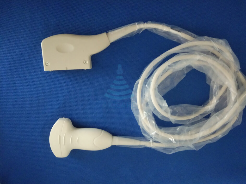
Answer first: Ultrasound probe connector identification starts with clear views of the contact face, housing, locking mechanism, cable entry and scale. Connector photos can narrow an ultrasound probe identity when they show the contact face, housing, locking mechanism, cable entry and scale. They cannot prove compatibility on their own. The final match still needs the probe label, host-system model and software context.
Editorial scope: This is a procurement and service-evidence guide. It does not replace the exact manufacturer’s instructions for use, a clinical procedure, a physical inspection, the equipment owner’s safety process or a quote-specific compatibility decision.
Evidence basis and limits
The cited regulatory, manufacturer, catalogue and peer-reviewed sources establish the document and evidence categories used here. They do not prove stock, condition, compatibility or performance for an uninspected item; those conclusions remain item- and quote-specific.
Ultrasound Probe Connector Identification: decision matrix
| Decision field | Evidence to collect | Why it matters |
|---|---|---|
| Contact face | Straight-on, sharp, glare-free photo | Shows pin/contact layout without perspective distortion |
| Housing front | Full connector outline | Captures keying and shell shape |
| Left/right sides | Both profiles | Shows rails, latches and asymmetry |
| Top/bottom | Locking and guide features | Records mechanical engagement details |
| Cable entry | Strain relief and orientation | Helps distinguish similar housings |
| Scale | Ruler beside housing, not over contacts | Adds dimensions without hiding features |
| Probe label | Same frame set and item reference | Prevents photos from two probes being mixed |
| Host port | System label and approved port reference | Adds context without attempting insertion |
Use a repeatable photo set
Place the disconnected connector on a plain surface, use diffuse light, keep the camera square to each face and preserve original resolution. Do not touch or mark electrical contacts for the photograph.
File identity matters as much as image quality
Use one item reference across label, connector and host-system photographs. A perfect connector image is unsafe evidence if it cannot be linked to the correct probe.
Write the conclusion in levels
Record observed features, likely family and remaining uncertainty separately. Do not change likely to compatible until the host-system evidence supports it.
A practical verification workflow
- Identify the item. Photograph the complete label, serial or internal reference, connector and full device. Use the same reference in filenames, the RFQ and shipping record.
- Record the request. State the host system, software context when relevant, intended product or service path and the observed symptom or purchasing need in plain language.
- Collect comparable evidence. Ask every provider for the same rows in the decision matrix. Keep representative catalogue imagery separate from photos of the offered or serviced unit.
- Resolve gaps before commitment. Leave unknown fields marked pending. A short model stem, broad category, logo, database hit or verbal assurance should not replace exact item evidence.
- Confirm the written boundary. The quotation or service record should state compatibility assumptions, condition, inspection or test scope, exclusions, availability, timing, shipping responsibility and remedy terms for that request.
Common evidence failures to avoid
- Contact face: leaving this undocumented weakens the record because it shows pin/contact layout without perspective distortion.
- Housing front: leaving this undocumented weakens the record because it captures keying and shell shape.
- Left/right sides: leaving this undocumented weakens the record because it shows rails, latches and asymmetry.
- Top/bottom: leaving this undocumented weakens the record because it records mechanical engagement details.
- Cable entry: leaving this undocumented weakens the record because it helps distinguish similar housings.
How to compare the final record
Read the evidence in three layers. The catalogue layer helps discover a possible model. The item layer connects photos, labels, condition and test records to one physical device. The commercial layer states what will be supplied or serviced and under which terms. A strong answer in one layer cannot fill a gap in another. For example, a correct catalogue match does not establish current stock, and a dated photo does not establish system compatibility.
Before approval, ask a second reviewer to check the exact model characters, connector family, host-system context and every unresolved field. This simple review catches copied model stems, mixed photo sets and scope assumptions that keyword matching alone cannot detect.
Keep an audit-ready decision record
Save the original-resolution photos, source links, document revisions, quotation and later inspection or acceptance record under the same item reference. Record who supplied each fact and the date it was checked. If a model, system, quantity, destination or service scope changes, open a new revision instead of silently overwriting the earlier answer. This preserves the reason behind the decision and prevents evidence collected for one configuration from being reused as a universal claim.
The final record should also identify what was not checked. Clear exclusions are useful: they show where an owner, manufacturer, qualified service provider or facility procedure must supply the next decision. An honest pending field is safer and more actionable than a polished but unsupported conclusion.
Browse the model-led ultrasound probe catalogue
Frequently asked questions
Can image recognition confirm compatibility?
No. It can classify visible features, but it cannot verify all electrical, software and system requirements.
What is the minimum photo set?
Contact face, all housing sides, cable entry, scale, full probe label and host-system identity.
Should the connector be inserted for a photo test?
No. Follow the equipment owner's approved connection procedure rather than improvising a fit test.
Related evidence guides
- How to Evaluate an Ultrasound Probe Supplier: 12 Pieces of Evidence to Request
- Philips Ultrasound Probe Repair: Model and Connector Identification Checklist
Sources and scope
Sources checked 3 August 2026. Use the current exact manufacturer document, facility procedure and jurisdiction-specific requirement for the device involved.